NET-1111 - Cisco 1 - Intro to Networks
Week 1 – Introduction to Networking & Course Setup
Description:
We were introduced to networks and the general devices that make up networks. We were also introduced to Cisco Packet Tracer.
Artifacts:
- Lab Assignment: Make a simple network with two hosts and a switch. Ping between the hosts.
Reflection:
My first impressions of networking come from using modem’s and connecting to local Bulletin Board systems. I was hooked. My dad brought home a bunch of old PC’s and ARCNet NIC’s from his work. And I hooked those up using the IPX and TCP/IP protocols. Also the internet was just emerging via local ISP’s. I got my first account with a local company named Green Apple in Lancaster, Ohio. Eventually, I upgraded my ARCNet network to Ethernet. At 16 I worked at a local computer shop installing and upgrading networks and servers for local businesses and doing support for the local ISP.
And today networking affects us to an even greater degree. Everything seems to be online. For example: the brake controller we just bought for our vehicle! We had to login to an app to configure it. I think it’s a little overboard to be honest.
I hope to learn how to configure cisco switches and routers. I’ve used active HP switches before to configure things like VLANs. I’m familiar with home-based routers like Linksys where you can put tailored versions of linux on them, like DD-WRT or Tomato and configured things like VPNs. I’ve configured firewalls with PF and PFSense on unix.
AI Use Note:
I haven’t used AI yet this course.
Week 2 – Networking Components, Types and Connections
Description:
We were tasked to represent our home network in Cisco Packet Tracer. I couldn’t find a smart tv and I suppose there are bluetooth devices, like speakers that aren’t being represented.
Artifacts: 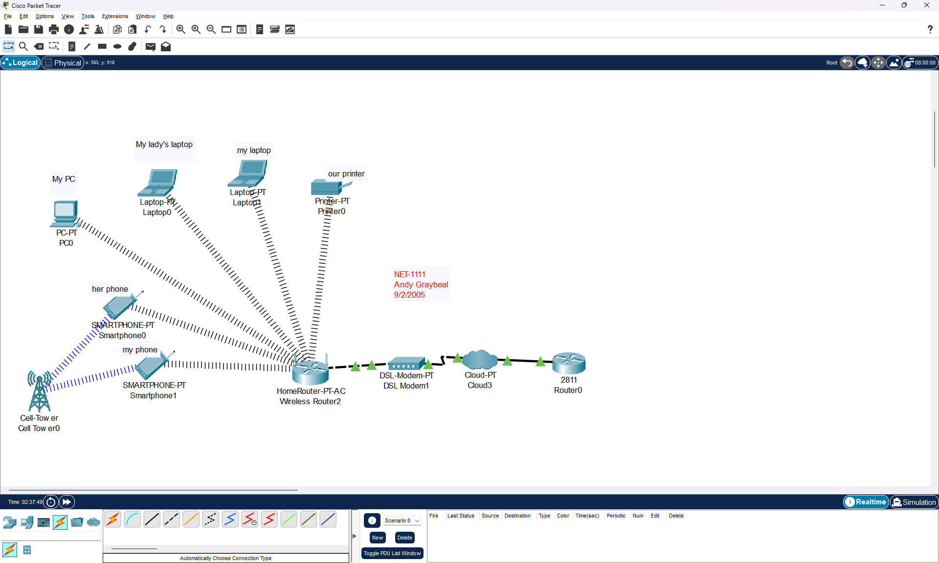
AI Use Note: I haven’t used AI.
Week 3 – Ethernet Fundamentals, Cabling, and Switching
Description:
Earlier this week, in a lab, we were tasked to make a network that uses Star Topology and to verify L2/L3 connectivity using Cisco’s Packet Tracer application. The prompt for this entry is this:
Polished post: “Star Topology” + screenshots from Lab. Use what you did in Lab (Day 1) assignment for this entry. Explain what a star topology is, what devices are required, what connections are used, > and what you had to configure on the end devices to get them connected.
Star Topology Network
The star topology is the name of a network topology or network configuration that consists of nodes that are connected to a central location. Each node is singularly connected with a cable to a central point looking like a spoke connected to a hub, like on a wagon-wheel. This hub can be one of two devices, namely a switch or a hub. Technically though, the specific device that we call a hub is a relic of technology and no longer in widespread use. This wagon-wheel type configuration appears to some to look like a star, hence it’s name: “Star Topology”. Other topologies exist, for example the “Bus Topology” which consist of a single line of nodes, appearing like a bus or another topology called a “Ring Topology” which connects nodes in a circle-fashion, looking like a ring. Each network topology has it’s own significance within networking techology.
Each node in a “Star Topology Network” consists of an end-device like a PC, Laptop, Printer, etc. Each end-device has an ethernet port connected to one end of an ethernet cable and that connects to an ethernet port on an ethernet switch on the other end of the cable. Each ethernet cable is configured with 4 pairs of wires, each pair twisted together, namely a “Twisted Pair”. The ethernet cable is designed this way to reduce noise. The connector on an ethernet cable is called RJ45 connector. RJ45 is a telecomunications wiring standard that has been applied to an 8p8c connector, or a 8 position 8 pin connector.
Each pair of wires in the cable are color-coded with solid and white-dashed colors: Orange, Green, Blue and Brown. The order of the wires in the terminated connectors of the cable has been defined by the TIA (Telecommuncaitons Industry Association) and ANSI (American National Standards Institute). They came up with two standards named T568A and T568B. Both do equally the same thing. The difference between the two standards is essentially the order of the orange pair and the green pair of wires have been swapped. The T568A standard is Green-White Green, Orange-White Blue, Blue-White Orange, Brown-White Brown. The T568B standard is Orange-White Orange, Green-White Blue, Blue-White Green, and Brown-White Brown. On each network, we cannot mix the standards though. T568A has been adopted by the government. T568B has been mostly used in, what I consider “everything else”. I’ve only ever seen T568B used. So just use the B standard and we will be good. By using either one of these standards to make the termination on both ends the cable, we have made what is called a “straight-through” cable. One neat thing is, if you use each standard to terminate the connectors on either end of a cable we have what’s called a “cross-over” cable. This cable is cool because in certain instances you might need such a thing, like connecting two end-devices together without a switch or for connecting older switches together.
Ethernet cables come in two types, Unshielded Twisted Pair (UTP), or Shielded Twisted Pair (STP). If we were experiencing lots of electro-magnetic interference, we would choose STP. More particularly, the cables come in stranded or solid wires. Solid wires are more rigid and prone to breaking if they experience lots of mechanical movement or fatigue. Stranded wires, on the other hand can handle lots mechanical movement without breaking. Solid wire cables are used behind the walls, and the stranded wire cables are used for our patch cords. Even more particularly, some of these cables can be used within plenum spaces and some cannot based on the particular type of plastic used in the sheathing. Following fire-code is an essential part of installing ethernet cable in a building.
Each end-device is assigned a MAC address, or Media Access Control address from it’s manufacturer. This address talks on what we call Layer 2 of the OSI (Open Systems Interconnection) model or the “Data-Link Layer” of the local network. Similarly, each device is assigned either manually or automatically (with DHCP (Dynamic Host Configuration Protocol) service) it’s own IP (Internet Protocol) Address. This address talks on Layer 3 or what is called the “Network Layer” of the local network. The ARP (Address Resolution Protocol) maps these two addresses together, essentially connecting Layer 2 to Layer 3 on the local network.
Basic switches communicate on Layer 1 and Layer 2 of the OSI layers, ie. moving data around based on MAC addressing. Some switches, called multi-layer switches also operate at Layer 3 and can be used for routing IP addresses across VLANs (Virtual LANs), these types of switches are used in larger organizations that require VLAN technology.
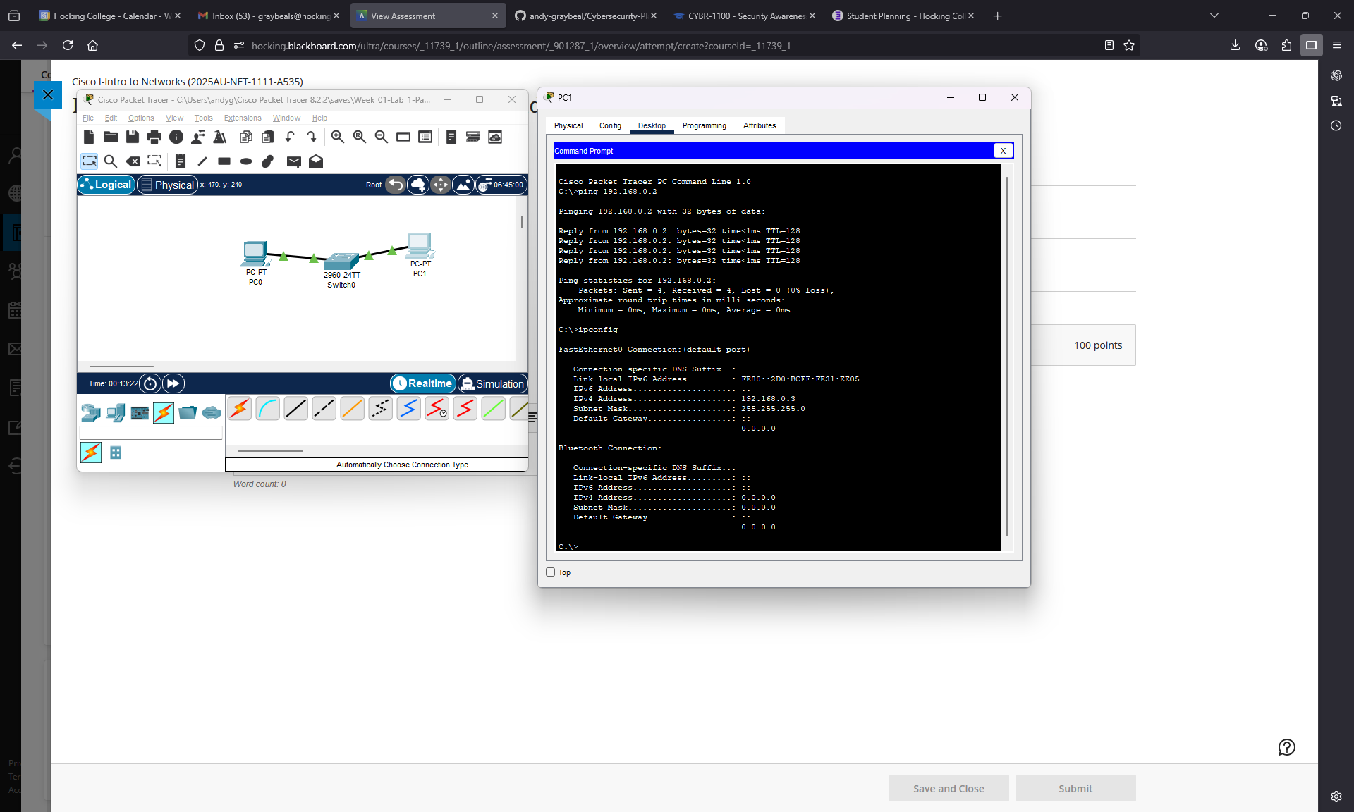
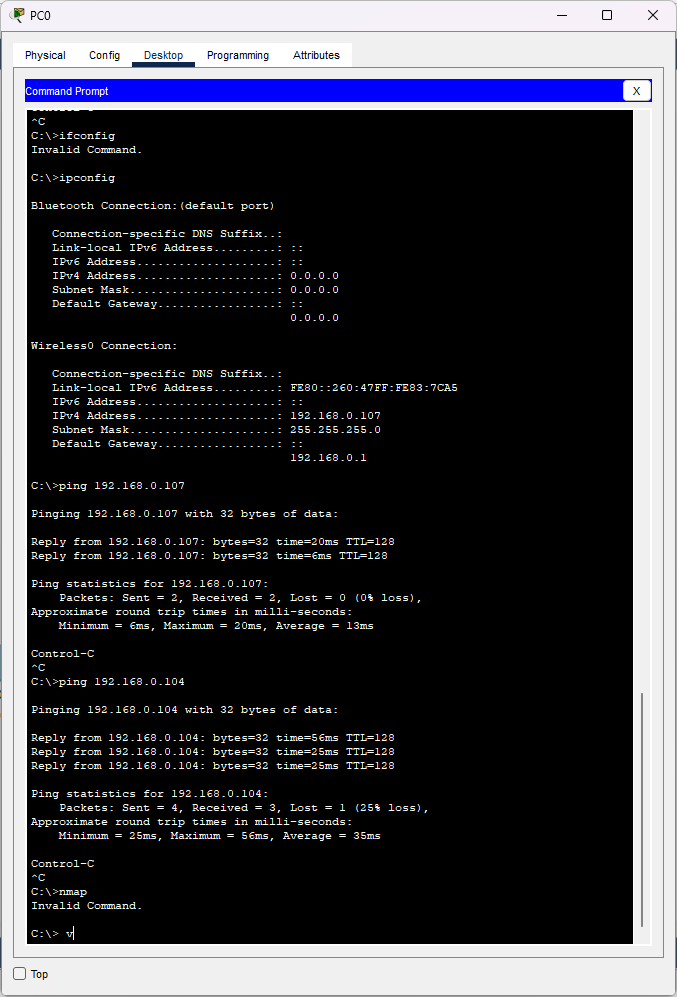
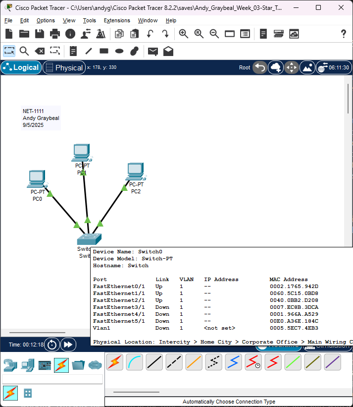
Pictured below are screenshots from Cisco’s Packet Tracer application showing my example of a “Star Topology Network” that I used in the previously mentioned lab. I used 3 PCs as the nodes, a switch as the central hub and I wired it with “straight-through” ethernet cables for my spokes. Each PC needed an IP address assigned to it manually or what we call statically because there is no DHCP server to automatically hand out addresses in such a simple network configuration. Like mentioned before, the MAC address is already assigned to each device from the manufacturer, so that’s already taken care for us.
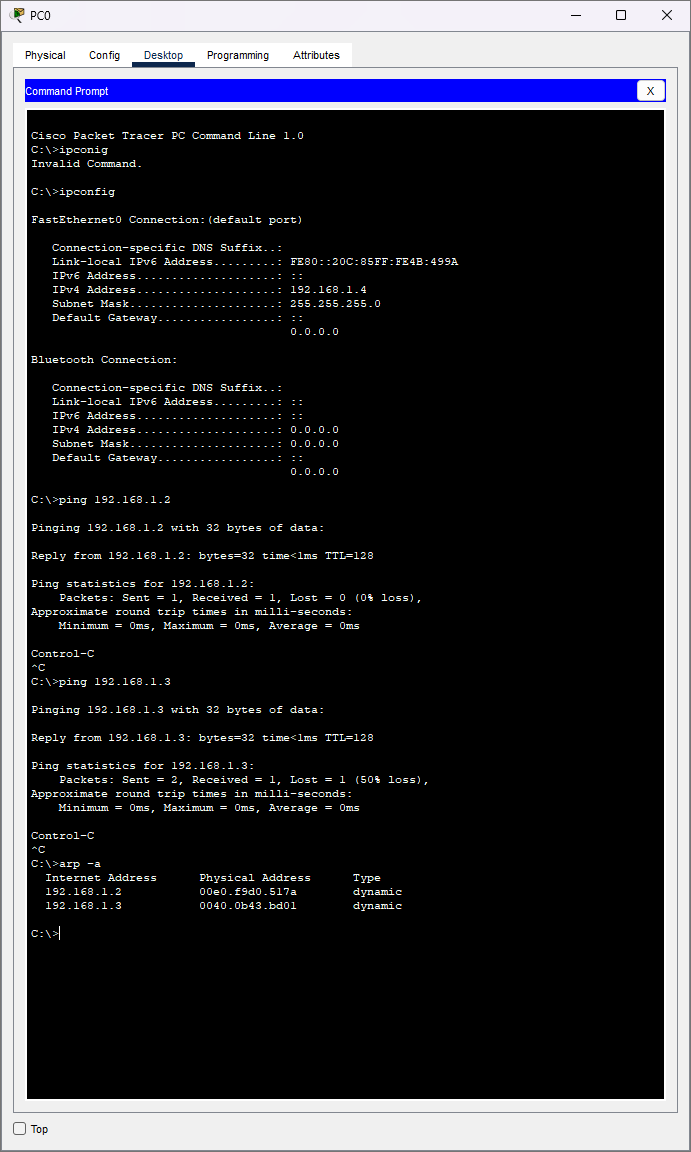
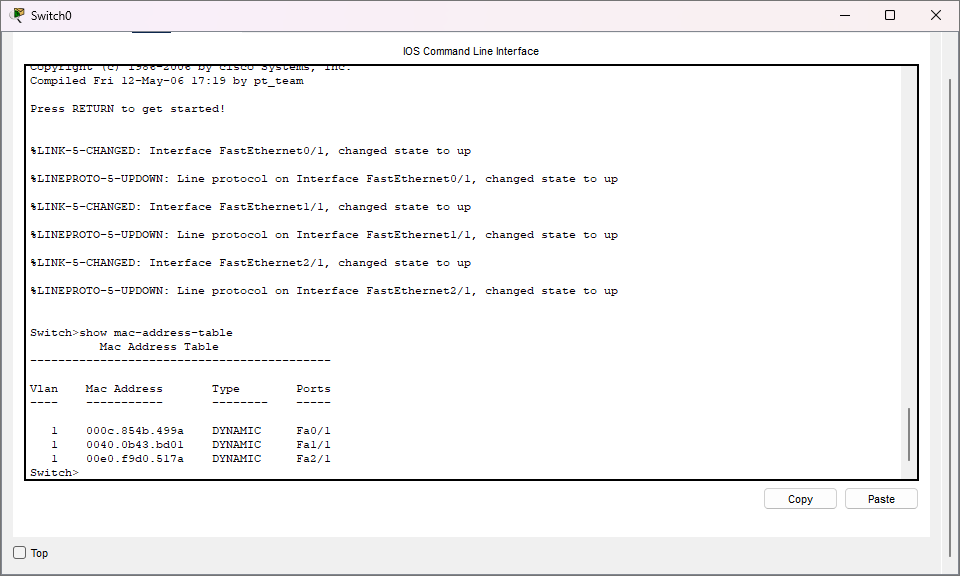
On the PC’s CLI I used commands like “ipconfig” to show the configuration of the network interface, “arp” to display the MAC address to IP address translation (Layer 2 and 3), and “ping” to show ip connectivity (Layer 3). On the switch’s CLI I used the “show mac-address-table” command to show the MAC addresses connected to the switch (Layer 2).
AI Use Note: I haven’t used AI.